In 2000, ASHRAE revised the basis for sizing pressure relief vent piping applied to refrigerating systems in its Standard 15 (Safety Standard for Refrigeration Systems). Since then, other standards such as IIAR 2 have undergone similar revisions and are consistent with the vent pipe sizing requirements in ASHRAE 15. The exception is the Uniform Mechanical Code (and California Mechanical Code) which still uses the outdated basis from the 1994 edition of ASHRAE 15.
Are you providing your customers with compliant safety relief systems?
In this article, our goal is to provide you with information to ensure your relief vent systems are not only safe but compliant as well. We will revisit the basics requirements for vent piping for pressure relief systems and dispel some myths in the process.
Introduction
ASHRAE Standard 15-2010 requires that refrigeration systems be protected from overpressure with the installation of a pressure-relief device (§9.4.1). A compliant safety relief system requires:
- A pressure relief valve/device with sufficient flow or capacity and set pressure for the protected component.
- Inlet piping and fittings to the relief valve that do not impose excessive inlet pressure drop.
- Relief vent piping appropriately sized to limit the back pressure during actuation and directed to a safe terminal location.
ASHRAE 15 provides an approach for the minimum required capacity of pressure relief devices for pressure vessels and positive displacement compressors. However, in some cases, pressure relief valves may be applied to other system components such as a heat exchanger. For these cases, additional information on capacity determination for equipment can be found elsewhere, such as Reindl & Jekel (2009).
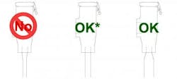
Section UG-135 of the ASME Boiler and Pressure Vessel Code includes the basic requirement that all piping, fittings, and valves (e.g. three-way valves) on the inlet side of a pressure relief valve must be equal to or greater than the inlet area of the relief device itself. UG-135 also states that “The characteristics of this upstream system shall be such that the pressure drop will not reduce the relieving capacity below that required or adversely affect the proper operation of the pressure relief valve.” Although our focus in this article is on the vent side of relief systems, it is easy to spot check the installation of relief devices to ensure they meet one aspect of the inlet size criteria. That is, the relief device inlet connection size cannot be larger than the component’s relief connection size as shown in Figure 1. For additional information on inlet piping or its effect on relief valve performance, see Reindl & Jekel (2006).
Limits to Outlet Connection Size Piping
Some relief valves used in the refrigeration industry have the combination of high capacity and small outlet connection size. ASHRAE 15 limits the pressure at the outlet of a conventional pressure relief device to 15% of the valve’s set pressure. As the capacity of a relief valve increases, the size of the vent pipe must necessarily increase to avoid elevated back pressure on the valve due to excessive pressure drop in the vent line.
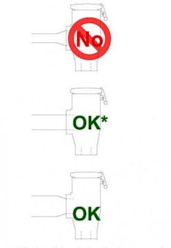
Section 9.7.8.4 of ASHRAE 15 states “The size of the discharge pipe from a pressure relief device or fusible plug shall not be less than the outlet size of the pressure-relief device or fusible plug.” Figure 2 illustrates examples of possible outlet piping sizes. The top illustration shows outlet piping smaller than the relief device outlet connection size in direct violation of Section 9.7.8.4 of ASHRAE 15. The middle case shows outlet piping equal to the outlet connection size of the valve. This is permitted as long as the calculated back pressure on the relief device is less than the maximum allowable back pressure (15% for conventional relief valves). Typically, this would mean the valve would be of a reduced capacity type or have a short outlet vent pipe length. The lower case shows vent piping larger than the outlet connection on the valve. This will be the usual circumstance for relief valves with moderate to large capacity. In this case, the transition to the larger vent pipe is made directly at the relief device outlet connection.
Installing a ¾-in. schedule 40 vent line on a 9 lb/min capacity valve would allow up to 54- ft. equivalent of pipe without exceeding the maximum allowable back pressure. Greater pipe lengths would not be compliant because the added pressure drop increases the back pressure on the valve above the maximum allowable back pressure of 37.5 psig (52.5 psia).
What is the effect of a larger capacity valve on the maximum allowable line length? If the valve in the previous example was replaced with one with a capacity of 44 lb/min, the maximum allowable line length would decrease to less than 1 ft.! Clearly, this is not sufficient and applying this valve would require the installation of a fitting on the outlet of the relief valve to accommodate the larger pipe size needed to prevent excessive back pressure on the valve as shown in the bottom illustration of Figure 2.
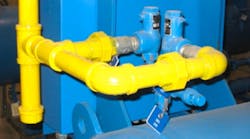
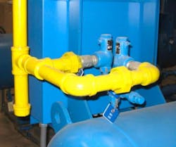
Figure 3 shows an installation of a dual relief assembly with vent piping that is upsized at the outlet of the relief device in order to limit the effects of pressure drop in the vent piping and achieve a compliant vent system. Figure 4 shows a single relief valve with piping upsized at the outlet.
Some believe that the need to increase the pipe size at the outlet of a large capacity relief valve to be compliant is the result of ASHRAE changing to the new line length formula back in 2000. That simply is not the case. For many of the relief valves used in refrigeration applications prior to 2000, upsizing the vent pipe at the outlet of the valve would have been required to comply with prior versions of ASHRAE 15 as well. Complying with the new relief piping requirements introduced by ASHRAE in Standard 15 - 2000 will generally require the vent piping to be one to two line sizes larger compared a relief vent pipe intended to comply with the old version of Standard 15 (1994).
CONCLUSIONS
Revisions to the calculations for sizing relief vent piping in ASHRAE 15 were made in 2000, and the practitioners using the “new” formula for relief vent line length limits experienced some degree of confusion when they used the formula and calculations resulted in very short (or negative) line lengths. This result simply requires that larger vent piping be used to achieve a compliant installation. To an extent, that confusion is persisting today because some new installations of safety relief systems are not compliant with a standard such as ASHRAE 15.
With the “new” method being required for more than a decade, there continues to be mistakes made on relief system vent piping installations that include:
- Relief vent piping installed in outlet connection size for larger capacity relief valves
- Outlet piping upsized from outlet connection size to larger pipe sizes well downstream from the relief valve outlet
-
Sizing of vent lines not consistent with the “new” line length limit provided in ASHRAE Standard 15.
TO READ THIS ARTICLE IN ITS ENTIRETY, PLEASE VISIT THE INDUSTRIAL REFRIGERATION CONSORTIUM ARCHIVES
