Oil separators are used on refrigeration systems where it’s difficult for the oil to return from the evaporator. These typically are field built-up systems, such as in supermarkets, and ultra-low temperature systems.
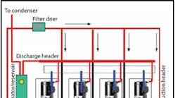
Oil separators are installed in the compressor/ compressors discharge line. They’re usually a vertical container with the discharge gas connections at the top and an oil return port at the bottom. This return line may be piped directly to the suction line on single compressor units or on multiple compressor racks would be piped to a holding tank called an oil reservoir. Some oil separators have a reservoir built into the bottom portion of the container with the upper portion being the separator.
From the reservoir, the oil is then returned to the compressors by use of a mechanical or electronic oil level control fastened to the compressor crankcase.
Oil separators use various modes of oil separation methods to remove the oil from the discharge gas as it leaves the compressor. These methods include reduction of velocity, impingement, centrifugal action, or coalescing elements. Oil separators vary in capacity and efficiency depending upon the mass flow that is being pumped through them and no oil separator is 100% efficient.
©2005 Emerson Climate Technologies, Inc. Used by permission.
Service Valve Maintenance
The typical service valve is composed of four essential parts:
• line connection
• valve stem
• service opening or gauge port
• compressor connection.
Typically, the service valve has a common connection that’s always open. When the valve is back-seated (the stem is all the way out), the gauge port is closed and the valve is open, allowing refrigerant to flow through the system. If the valve is front-seated (stem all the way in), the gauge port is open to the compressor connection and the refrigerant line (suction or discharge) connection is closed.
In order to read the pressure while the valve is open, the valve should be back-seated, then turned once or twice to slightly open all three connections: the gauge port, line, and compressor. This allows both the compressor and refrigerant line to be open and vapor pressure to flow through. At the gauge port, you can check system pressure and charge or reclaim refrigerant.
When brazing a service valve:
Make sure the valve is mid-seated before brazing. The heat from brazing a fully front-seated or back-seated valve can cause the button of the valve stem (inside the valve) to ‘weld’ to the seating area on the inside of the body of the valve.
A technique called ‘wet-ragging’ can also help. Soak a rag in cold water and wrap it around the service valve before brazing. Make sure water does not enter the valve.
When opening a service valve:
Make sure the service valve is secure (in a vice, bolted down, or attached with the rotalock connection) before attempting to open the packing nut or valve stem. Verify whether the valve employs a packing gland nut (many Copeland® brand service valves do). The packing nut helps to ensure a leak free seal. It is typically brass and is found at the base of the valve stem (see illustration on other side). It must be loosened by a 1/4 to a full turn before opening the valve. Make sure to tighten the nut when you are finished manipulating the valve stem. Use the right tools! Service valves on Copeland® brand condensing units have a torque requirement of 22-25 ft lbs. in order to have a leak free seal when the units leave our plant. You will only be able to open a service valve with the appropriately sized service valve wrench. Do not attempt to open a service valve with an adjustable wrench. You may round the valve stem edges and the valve will be useless. If all else fails and the stem appears stuck, lightly tap the end of the valve stem with a hammer and the valve should open. (NOTE: If the packing gland nut is not loosened, the valve could be damaged.)
©2005 Emerson Climate Technologies, Inc. Used by permission.

