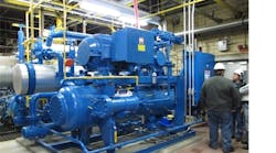
The trend of increased focus on energy conservation and sustainability is clear. Due to recent high pressure screw compressor developments, the industrial refrigeration industry is positioned to employ ammonia heat pump systems to harvest waste heat and to enhance the profitability and environmentally sound operation of food and beverage processing facilities.
This paper details the development, design, installation and operation of an ammonia heat pump system at a food processing facility in Iowa. The installation was completed as an addition to an existing industrial refrigeration system, and the savings generated by its operation are now occurring. These savings have been measured and will total hundreds of thousands of dollars annually.
Iowa Facility Project
The facility in Davenport, Iowa, by conventional standards, had made significant investments in energy conservation. With years of leadership focus on energy savings, the plant already employed high efficiency boilers and invested to capture and recover boiler stack heat.
Yet, like many food processing plants, they were paying for electrical energy to remove heat from their refrigerated spaces via an ammonia refrigeration system and rejecting that heat to the atmosphere. Additionally, they were paying for natural gas to add heat to hot water used for the hygienic cleaning of the facility.
If the rejected heat could be captured and used to provide water heating, substantive amounts of energy would be saved. The highest pressures and temperatures in the refrigeration system (compressor discharge gas) provided the optimal source for heat to be transferred to the clean-up water. However, as ammonia refrigeration practitioners who have employed “heat reclaim” practices have noted, ammonia at typical condensing pressures while possessing large quantities of heat energy, condenses at relatively low temperatures [75-95F (24-35C)]. As such, the transfer of this energy to city water, through conventional heat exchangers, to create 145-185F (63-85C) wash down water, is only effective for limited pre-heating of the cold water supply.
If the refrigeration system compressor discharge gas, at relatively high pressures [180 psig (13.2 atm)] could be fed directly into the suction of a “heat pump” compressor and compressed to even higher pressures [i.e. 450-800 psig (32-55 atm)], condensing this higher pressure ammonia with cold water in a heat exchanger would capture much larger quantities of heat energy than heat reclaim, and enable, in this case, the full temperature elevation of the cold water supply from 60F (15C) up to the 145F (63C) required for wash down.
The requirement of the facility to have the wash down water classified as a potable supply presented another challenge, as local codes prohibit the use of potable water to be in direct heat exchange with ammonia. Employment of such an ammonia heat pump system would require the use of a secondary loop, thereby reducing the efficiency of heat transfer.
Given the need for sustainable projects to clear the same internal rate of return hurdle as non-sustainable projects, the challenge was to define and justify the project. The project costs would include tapping into an existing ammonia refrigeration system, adding and installing a custom ammonia heat pump system and employing the electrical energy to operate the high pressure ammonia heat pump system. As will be discussed, the returns would include savings in reduced natural gas usage, as well as evaporative condenser electrical and water savings due to reductions in evaporative condenser loading.
Project Definition
Boiler stack economizers satisfy a base hot water load for the plant’s sanitation requirements. Supplemental heat for hot water is also provided by a direct contact natural gas fired hot water heater. It was intended that the new ammonia heat pump system would replace the use of the direct contact hot water heater which delivers an estimated average heating capacity of 5.156 MMBtuh (1,511 kW) when heating 125 GPM (28.4 m3/h) from an average 62.5F (16.9C) up to 145F (62.8C), with the understanding that an even greater flow rate of water could be utilized.
In summer operation, it was desired to heat 205 GPM (46.6 m3/h) of cold well water from 65F (18.3C) to 145F (62.8C) [approximately 8.200 MMBtuh (2,400 kW)] through a secondary plate and frame heat exchanger, supplying hot potable water to the facility’s existing 55,000 gallon (208 m3) hot water storage tank. Heat energy would be provided by heat extracted from process loads of the plant’s existing ammonia refrigeration system, plus the heat of compression from the plants existing compressors and the new heat pump compressor.
Summer condensing pressures were modeled at 160 psig (11.9 atm), and winter condensing pressures at 105 psig (8.1 atm). The lower winter condensing pressures would require a greater lift by the heat pump compressor than with the higher summer condensing pressures. Together with the lower 60F (15.6C) incoming cold water temperature during winter, the estimated heating capacity of the heat pump during winter conditions was estimated at 5.738 MMBtuh (1,682 kW), providing 135 GPM (30.7 m3/h) of continuous 145F (62.8C) hot water flow.
The heat pump was estimated to provide an average heating capacity of 7.013 MMBtuh (2,056 kW), heating 170 GPM (38.6 m3/h) from 62.5F (16.9C) to 145F (62.8C).
A solution of 10% propylene glycol (with corrosion inhibitors) and water would be circulated between the ammonia heat pump system and the heat supply side of the plate and frame heat exchanger. This solution would be pumped via a separate secondary loop pumping system, receiving heat by providing condensing to the ammonia heat pump system and transferring this heat to the incoming cold water through the aforementioned plate and frame heat exchanger.
System Description
The flow of refrigerant through the ammonia heat pump system would be routed from the compressor discharge of the plant’s refrigeration system into the heat pump package, flowing through a desuperheater, then the single screw heat pump compressor unit, a shell and tube condenser, a shell and tube subcooler, a pneumatic expansion valve, and back to the condensed liquid side of the existing refrigeration system. Propylene glycol at 75F (23.9C) would flow through a secondary loop from a plate heat exchanger through the heat pump, circuited initially through the subcooler, then desuperheater, oil cooler, condenser, and returning to the plate heat exchanger at 155F (68.3C) (See Figure 1).
With the understanding of the intent to collect data, monitor heat pump performance and share the performance results with the ammonia refrigeration industry, the heat pump was to be fitted with a SCADA (supervisory control and data acquisition) system to continuously monitor the system operation. The SCADA system would collect measurements provided from 29 data points every second and save this to a database, automatically generating reports for each 24 hours of data.
Key measurements that would be gathered, included, but were not limited to:
Cold Water: Cold Water Plate Heat Exchanger Inlet temperature
Cold Water Plate Heat Exchanger Outlet temperature
Cold Water Flow rate (Rosemount flow transmitter)
Secondary Loop:
Glycol Solution Plate Heat Exchanger Inlet temperature
Glycol Solution Plate Heat Exchanger Outlet temperature
Glycol Solution Flow Rate (Rosemount flow transmitter)
Subcooler Inlet/Outlet Temperatures
Desuperheater Inlet/Outlet Temperatures
Oil Cooler Inlet/Outlet Temperatures
Condenser Inlet/Outlet Temperatures
Ammonia heat pump:
Compressor motor power (Schneider Electric KW meter installed inside starter)
Multiple pressures and temperatures points throughout the ammonia piping of the heat pump package.
In preparation for the installation of the ammonia heat pump system, the existing ammonia refrigeration system would be prepared with the addition of pipe stubs and isolation valves. These would be located at the existing compressor discharge gas header and the condenser return liquid header. The discharge stub would be piped to the suction of the heat pump and the liquid stub piped to the outlet of the liquid subcooler.
Expected Results
The coefficient of performance (COP), a term more commonly used in the HVAC industry, is the ratio created by dividing the beneficial energy supplied to the system by the energy required to develop the benefit.
In a fossil fuel fired boiler or heater, the COP can never be more than one and is less than one due to heat losses to the surroundings and through discharge stacks.
For the ammonia heat pump the COP is a division of the captured, and otherwise rejected, heat from the existing ammonia system and the captured heat of ammonia heat pump compression, as transferred to the cold water flow, divided by the work energy used to operate the ammonia heat pump system.
COP calculated for summer design conditions:
Heating 205 GPM (46.6 m3/h) of water from 65F (18.3C) to 145F (62.8C)
Q= mC∆T
A nominal MBH calculation, with correction factors for water flow in GPM, water specific gravity = 1.0 and water specific heat = 1.0, is as follows:
MBH = (205 GPM x 1.0 x (145oF- 65oF) x 500)/1000 = 8,200 MBH
Work is the power absorbed in the compressor crankshaft divided by motor efficiency
In the case of this design, work = 564 BHP/ 95% = 594 HP
As COP is a dimensionless value, common units are required, so, converting to kW:
Energy benefit = 8,200 MBH/3.41 = 2,405 kW
Energy input = 594 HP/ 1.34 = 443 kW at 160 psig (11.9 atm) [88F (31°C)] saturated suction and 510 psig (35.7 atm) [165F (73.9C)] saturated condensing.
COP = 2,405/443 = 5.43
COP calculated for winter design conditions:
Heating 135 GPM (30.7 m3/h) of water from 60F (15.6C) to 145F (62.8°C)
Q =mC∆T
MBH = (135 GPM x 1.0 x (145F – 60F) x 500)/1000 = 5,738 MBH Work = 534 BHP/ 95% = 562 HP
Energy benefit = 5,738 MBH / 3.41 = 1,682 kW Energy input = 562 HP/ 1.34 = 419 kW at 105 psig (8.1 atm) [65.8F (18.8C)] saturated suction and 510 psig (35.7 atm) [165°F (73.9C)] saturated condensing.
COP = 4.01
A detailed heating load profile for the heat pump would have been ideal but was unavailable. For initial evaluation purposes, we used an average value, assuming steady variation from winter (minimum load) to summer (maximum load) conditions, yielding:
MBH = (170 GPM x 1.0 x (145F -62.5F) x 500)/1000 = 7,013 MBH = 2,056 kW
Work = 549 BHP / 95% = 578 HP = 431 kW
COP = 4.77
Utilizing these values, with the natural gas cost for the Davenport facility at $7/MMBtu and electrical costs at $.045/kW, we can compare the two alternate means of generating heat energy at the facility.
Direct Contact Water Heater Evaluation
For a direct contact water heater, a nominal efficiency of 97%, COP = .97, this facility can provide the average value of hourly heat energy at the following cost profile:
Energy input to heater = 7,013 MBH/ .97= 7,230 MBH
7,230 MBH = 7.23 MMBtuh, 7.23 MMBtuh x $7.00/MMBtu = $50.61/hour.
Heat Pump Evaluation
Energy input to ammonia heat pump = 431 kW 431 kW x $.045/kWh = $19.40/ hour.
Operating Savings
With facility operation planned at 24 hours/day, 7 days/week and 51 weeks a year (8,568 hours/year), annual operating savings using the ammonia heat pump system in lieu of a boiler can be calculated as follows: ($50.61 - $19.40) x (24 x 7 x 51) = $267,407 per year.
Other Costs
It should be noted that the aforementioned savings are realized despite the indirect heating occurring through the operation of a secondary loop. The compressor work required would be less in a direct heating system.
But, since it is a secondary loop system, one should consider the operation of the glycol/water pump as an energy consumer. With its motor controlled by a VFD, we calculated the glycol pump operating costs as follows:
5 BHP/75% = 6.7HP = 5kW
5kW x $.045/kWh = $.225/hr, $.225/hr x 8,568 hours/year = $1927.80 additional cost per year.
Other Savings
To the existing ammonia refrigeration system, the ammonia heat pump system acts as a condenser. Compressor discharge gas is diverted before reaching the evaporative condensers, is routed to the ammonia heat pump system, and returns as condensed liquid. It was expected that the 7,000 MBH (2,050 kW) of additional condensing capacity of the heat pump would reduce the condensing pressure of the existing refrigeration system, or if operated at minimum allowable condensing pressure of 105 psig (8.1 atm), would offset the operation of the equivalent capacity of existing condensers. It was estimated that the existing system would operate roughly half of the year with floating head pressure, allowing full condenser operation with condensing pressure fluctuations based on corresponding ambient wet bulb temperature, and the other half of the year at the minimum condensing pressure of 105 psig (8.1 atm), by adjusting condenser fan and pump operation.
During summer operation, the added condensing capacity of the heat pump would result in a reduction of the high stage condensing pressure by an estimated 4 psi (0.3 atm), reducing the existing system’s power consumption by 105 HP (78.3 kW), for approximately $15,037 in additional savings.
During winter, with the existing refrigeration system operating at minimum condensing pressure, the condensing capacity of the heat pump would reduce the utility consumption of the equivalent capacity evaporative condensers, offsetting 90 fan horsepower and 15 pump horsepower for approximately $15,080 in additional savings.
Water Savings
The 7,000 MBH (2,050 kW) of additional condensing capacity of the heat pump would reduce the evaporative condenser water consumption by approximately 4.8 GPM/100 tons, of which 2.4 GPM evaporates and 2.4 GPM drains to sewer (blowdown) for each 100 tons of condenser load. The 28 GPM (6.4 m3/h) of curtailed water use would save more than 14 million gallons (53,000 m3) of consumed water, and 7 million gallons (26,500 m3) of water drained to sewer per year. It should be noted that substantive water treatment savings will also occur.
Detailed System Description
When the installation and operation of an ammonia heat pump system was justified by demonstrating a significant return on investment, more specific details of the system to be installed were developed.
Two skid-mounted packages were to be built, one consisting of the secondary coolant pumping system and plate and frame heat exchanger. On the other skid the ammonia heat pump components were mounted, including a desuperheater, the single screw heat pump compressor unit, compressor motor, oil separator, oil cooler, condenser, liquid subcooler and a PLC controller.
Ammonia gas discharged from the existing refrigeration system’s compressors enters the ammonia heat pump through the operation of a motorized control valve. The gas is drawn into the heat pump system desuperheater. The two-pass desuperheater lowers the temperature of the superheated gas to within 20F of saturation, while providing a source of heat to the secondary loop. A three-way valve is provided to by-pass gas if the approach drops below 20F. The lower temperature gas helps ensure that oil temperatures in the heat pump compressor do not exceed recommended levels. The gas is then directed to the suction of the ammonia heat pump compressor.
The operation of a single screw compressor, which can receive suction gas up to 400 psia (27 atm) or higher, is not limited by suction pressure. The highest efficiency and greatest amount of heat delivered from the heat pump occurs when operating at the highest possible suction pressure, which corresponds to the highest discharge pressure from the existing refrigeration system.
Special materials of construction are used for compressor housings on systems requiring higher temperature water (and correspondingly higher heat pump compressor discharge pressures) than the 145F (62.8C) water requirements of the facility. The high discharge pressure controls for the heat pump system are set to alarm at 530 psig (37 atm), and trip at 540 (37.7atm) psig with relief valves set for 600 psig (41.8 atm), and with the compressor housing designed for a maximum pressure of 750 psig (52 atm).
After compression to 512 psig (35.8 atm), the ammonia is routed through the heat pump impingement oil separator. Oil from the separator is recirculated, filtered and cooled via an external oil cooler which removes some of the heat of compression and transfers that heat to the secondary loop.
After leaving the oil separator, the high pressure gas enters the shell of a shell and tube condenser, transferring heat to the secondary loop via the glycol/water mixture flowing through the tubes of the condenser, and condensing as high pressure liquid.
Further heat is transferred to the secondary loop by subcooling the high pressure condensed liquid in the ammonia heat pump subcooler.
In total, there are four points where heat from the heat pump system is added to the secondary loop. These are the desuperheater, the oil cooler, the condenser and the subcooler. From the chart depicting the relative value of each of the heat sources (Figure 4), it's clear that the greatest source of heat energy for water heating is provided by the condensing of ammonia at the high pressures and temperatures of the heat pump system, a key differentiator between heat pumps and the sensible “heat reclaim” of discharge gas and oil heat of the past.
Operation
Although the application of the ammonia heat pump was new to the Davenport refrigeration operators, the components that make up the heat pump package are familiar to most operators. Most refrigeration systems currently have components for desuperheating, subcooling, compression and condensing. A process hazard analysis was conducted for the heat pump installation and included operators, the contractor, Emerson engineering and engineering from the food manufacturer. Risks were evaluated and recommendations were incorporated into the design. The operation of the heat pump is highly automated to respond to varying operating conditions for the ammonia and hot water systems. The heat pump automatically starts and stops based on the demand for hot water. The operator interface screens for the heat pump included graphics and data tables that were easy to view to verify proper operation. As a result, there is very little input needed from the operators on a daily basis. The operators quickly picked up the concept of the heat pump and became comfortable operating it.
Maintenance
Maintenance requirements for the heat pump are really no different than what is already required for existing compressors, vessels and heat exchangers.
Actual Results
The heat pump system’s capacity and efficiency varies with the existing refrigeration system’s condensing pressure and the temperature of the supply water to be heated.
During the height of summer, when the existing refrigeration system’s condensing pressure—and the heat pump’s suction pressure—peaks, the heat pump compressor’s differential pressure is at its lowest, and the resulting heat pump capacity and COP are at their highest.
The heat pump provides a constant year-round potable water temperature of 145F (62.8C), yet the supply water temperature of the potable water varies by season. The supply water temperature to the heat pump during the summer got as high as 68F (20C), and can drop to as low as 60F (15.6C) during the winter. The greatest differential temperature of the water to be heated, and thus the greatest heat pump duty, occurs during the winter.
Both — the condensing pressure of the host system and the supply temperature of the water to be heated — positively affect the heat pump performance during the summer and negatively affect the capacity and efficiency of the heat pump during the winter.
COP results for summer conditions, high suction pressure and high water flow: Data collected from the SCADA system for Wednesday, July 20, 2011 from 2:35 pm through 4:15 pm is shown in Figure 5. For a measured average flow rate of 209.9 GPM, heating 68.4F (20.2C) water to 145.4F (63.0C), delivered 2,369.5 kW of heat (8,080.6 MBH), operating at 185.2 psia (12.6 atm) suction and 492.4 psia (33.5 atm) discharge pressure, while consuming 364.0 kW power, providing an average 6.5 COP.
COP results for intermediate suction pressure and intermediate water flow conditions:
Data collected from the SCADA system for Tuesday, August 16, 2011 from 5:00 am through 6:00 am: For a measured average flow rate of 144.9 GPM (32.9 m3/h), heating 67.1F (19.5C) water to 145.0F (62.8C), delivered 1654.1 kW of heat (5,641.0 MBH), operating at 140.1 psia (9.5 atm) suction and 476.5 psia (32.4 atm) discharge pressure, while consuming 347.1 kW power, providing an average 4.8 COP.
COP results for low suction pressure and low water flow conditions: Data collected from the SCADA system for Thursday, September 22, 2011 from 2:00 am through 3:00 am: For a measured average flow rate of 125.7 GPM (28.5 m3/h), heating 67.8F (19.9C) water to 145.1F (62.8C), delivered 1423.6 kW of heat (4,857.6 MBH), operating at 125.1 psia (8.5 atm) suction and 477.4 psia (32.5 atm) discharge pressure, while consuming 336.9 kW power, providing an average 4.2 COP.
Higher summertime COP’s translate into greater summertime energy savings.
Although electric energy has a higher corresponding cost than natural gas in regard to heating energy, the greater quantity of natural gas required to produce an equivalent amount of heat energy as the heat pump translates into substantial net utility cost savings (See Figure 2).
Recommendations and Conclusions
Food processing often requires both refrigeration and hot water. Each of these needs have generally been met by independent utilities: consumption of electricity for the extraction and rejection of low grade heat, and fossil fuels for the production of high grade heat. The addition of an industrial heat pump provides for the renewal of the electrical energy consumed in producing a refrigeration effect by converting the low grade heat of rejection into useable high grade heat. Using the heat extracted by refrigeration in lieu of fossil fuels results in more than a five-fold reduction of energy consumed to produce an equivalent amount of hot water, with further savings of reduced power and water consumed by the system’s existing compressors and condensers.
The Davenport heat pump package met the original intent of the application, displacing the operation of the natural gas burning direct contact water heater, and the associated energy savings. Yet the heat pump package provided for the application has a greater capacity than the expected hot water load. As a result the heat pump package operates less time per day (8 to 14 hours) than the continuous operation that was anticipated. A smaller heat pump package with greater operating hours could have met the facilities hot water needs.
In deciding to utilize the site’s existing 55,000 gallon (208 m3) hot water storage tank in conjunction with the heat pump, the size of the tank constrains the operating hours of the heat pump package, further contributing to the reduced run time of the heat pump. A larger tank would provide storage of more hot water and enable longer run time hours of the heat pump than with the existing tank. Prior to applying a scavenging heat pump to an existing ammonia refrigeration system, an audit of the utilities and devices that would be affected by the use of the heat pump should be performed.
A complete audit would include:
• hot water load profiles including sanitation, water heated at point of use by steam, CIP, ingredient water, scalding, blanching, pasteurizing, boiler preheating, bottle washing, and bottle warming
• refrigeration system operating conditions and load profiles
• daily and seasonal weather data
• seasonal supply water temperature fluctuations
• utility cost data [electric, fossil fuel, water, sewer, treatment chemicals (condenser and boiler/water heater), water softening chemicals] including time of day and seasonal rates and demand charges where applicable
• boiler and water heater emission charges, pollution permitting, and pollution control and abatement costs
• estimated condenser and boiler/water heater service and maintenance requirements
Unlike conventional industrial refrigeration systems that are designed for operation during the hottest times of summer, the design conditions for the scavenging heat pump for this facility occurs during the coldest days of winter, due to the low operating discharge pressure from the host system compressors and the colder city water temperatures coming to the plant during the winter months. The design conditions for scavenging heat pumps may not always occur during the coldest seasonal conditions, though.
The addition of a scavenging heat pump to an existing industrial refrigeration system is analogous to adding another stage of refrigeration to the system: a second stage to a single stage system or a third stage to a two stage system. A two-stage ammonia refrigeration system optimized for highest energy efficiency would operate the compressors at the lowest possible compression ratio. In practice, consideration must be given for seasonal ambient temperature and corresponding condensing pressure fluctuations, refrigeration loads and corresponding suction pressure requirements, and the ratio of the high stage refrigeration compressor capacity to the compressor capacity of the heat pump stage.
A scavenging heat pump compressor operates at a steady condensing pressure to achieve a constant hot water temperature. A host/scavenging two-stage ammonia heat pump system optimized for highest energy efficiency would also operate the compressors at the lowest possible compression ratio. With a fixed suction pressure of the host compressors corresponding to the required refrigeration duty, and fixed discharge pressure corresponding to the required hot water temperature, consideration must be given to the ratio of host compressor capacity to scavenging heat pump compressor capacity in determining the optimum intermediate (host discharge/heat pump suction) pressure.
Many points of data are collected by the heat pump PLC controller that reveal detailed operating conditions of the package, enabling a clear understanding of the performance of the heat pump and the resulting savings in heat energy. Many ancillary savings are also realized with the installation of a heat pump that cannot be measured directly by its controls. These ancillary savings come from reduced condensing pressure of the existing compressors, offset condensing capacity and corresponding condensing utilities and maintenance, offset water heater emissions, permitting, and maintenance.
When the heat pump was energized, a noticeable drop in head pressure was observed, resulting in an improved efficiency of the existing refrigeration compressors. Monitoring the power of the compressors before and after the installation of a heat pump would reveal the actual savings.
Likewise, the additional condensing capacity provided by the heat pump resulted in a corresponding reduction of condenser water consumption by evaporation and blowdown and water treatment chemicals, and reduction in corresponding condenser capacity when the existing system’s head pressure dropped to the minimum level. Monitoring condenser performance before and after the installation of a heat pump would reveal the actual savings in fan and pump electric energy, water, sewer and chemicals.
This article is based on a presentation by Sam Gladis — business director, heat pumps, for Vilter Manufacturing, LLC, a business of Emerson Climate Technologies — at ATMOsphere 2012. He can be reached at [email protected] or by phone, at 414/486-5077.

