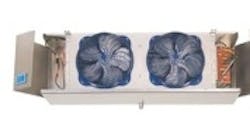
When a service technician is asked to troubleshoot a problem evaporator, some initial planning and prep work can help simplify the process. By addressing the problem in a sequential and methodical manner, the troubleshooting (and repair) time can be greatly reduced. This strategy has four basic areas: general equipment layout, unit-specific observations, defrosting/icing concerns, and finally, condensing unit observations.
General Equipment Layout
Recording data on an audit sheet provides a record of the type of equipment, application desired, temperature difference (TD) design, thermostatic expansion valve (TXV) selection, nozzle selection and at what conditions, unit balance, and other issues.
On the job, first listen to your customer's main concerns and issues, and take notes. Gather all the information available about the installation, such as current operating conditions, evaporator placement, drain installation and placement, and ambient temperature entering the doors that service the cooler/freezer.
Consider Piping, Power & Product
Observe the piping layout and suction line traps at the bottom and top of risers. Pipe runs may need to be insulated, especially when run through coolers or freezers. Liquid and suction lines need to be sized correctly for capacity requirements, proper oil return velocity, and flow through any branch circuits. Incorrectly sized suction and liquid lines can have problems outside and inside the box.
Review the supplied electrical power, the racking and/or shelving installation, and the type of product stored in cooler/freezer. Note the cooler condition as far as type of insulation and age, the doors, floors (concrete or insulated), conveyers or motorized loads within the box, and the number of people working inside the refrigerated area.
Unit Specific Observations
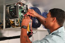
Evaporator motors, fan blades, and motor mounts need to be in correct operating condition in order to ensure proper air flow across the evaporator. The other electrical issue needing attention will be the defrost heaters and their correct placement on the coil and operation. Lastly, review the supplied electrical components. Make sure all electrical connections are secure, and all components are connected correctly.
Observe the condition of the evaporator unit, and collect current operation information.
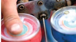
Examine the coil surface for frost or accumulated dust. Unrestricted airflow is absolutely critical with evaporators. Obtain the suction pressure at the evaporator in order to correctly calculate the superheat at the TXV.
Be observant of the refrigerant feeding supplied to the evaporator by the expansion valve and the distributor assembly. The ability of the evaporator to efficiently exchange heat is totally dependent on having a fully-active coil, as near to the saturated suction temperature of the refrigerant as possible. Remember, superheat can be correct even with incorrect refrigerant distribution.
Defrosting/Icing Concerns
The electrical compartment is often overlooked when it comes to proper operation. A common issue with the electrical panel is ice accumulation inside the compartment. This can result from the electrical conduit not being vapor tight, and allowing moisture to flow into the compartment. This moisture-laden vapor will collect on all cold components, resulting in a large ice or frost accumulation inside the compartment.
This icing condition can adversely affect defrost termination and fan control operations, leaving defrost heaters operating longer than needed. Left on too long, heaters can creep or even pop out of their heater slots. Defrost heaters can suffer damage resulting from excessive ice or frost that harms the electrical wiring itself, or the rubber boot connections.
A sufficient and correctly timed defrost schedule is necessary in order to completely defrost the evaporator at each cycle. If the evaporator and condensate pan do not completely clear, the accumulated frost load from each incomplete defrost cycle will eventually form "hard ice," and will create a problem. Remember, defrost heaters are designed to remove the crystalline hoar frost that collects during the cooling cycle, and are not designed to remove accumulated ice and frost.
Poor defrosting and unusual ice build up in the corners of the evaporator, and around TXV and distributor tubes, is often observed. Reasons for this can be incorrect drain installation (coils incorrectly connected to a common drain line), and coils not defrosting at the same time. Even though a trap is installed in the common drain line, the moisture from one coil in defrost can, and will, be transmitted to any other coils in a cooling cycle. This is no different than not using a P-trap. Moisture will always travel to the coldest place in the system.
Condensing Unit Observations
Suction pressure, suction line temperature, liquid line pressure, liquid line temperature, and correct operating charge at the condensing unit are necessary to properly make a complete system diagnosis. Correct superheat range at the compressor is the only crucial superheat, and is extremely important in the proper operation of the refrigeration system.
Superheat on a discus compressor should range between 15 and 25F in order to protect the compressor from flooding, or more importantly, from overheating. Superheat for scroll compressors is much lower, ranging from 10 to 20F.
Serious compressor damage will result when operating outside the above conditions. Frost at the compressor does not necessarily mean low superheat, and no frost at the compressor certainly does not mean there is sufficient superheat.
By breaking down evaporator troubleshooting into manageable pieces, the process of determining a solution is simplified.
| Galen Holzhausen is senior factory service engineer for Heatcraft Refrigeration Products. Call 770/465-5600 for assistance with any unit cooler troubleshooting issue, or visit www.heatcraftrpd.com. |
