Basic Hydronic Heating Components and Their Role in A System
Many of us focus on the airside of HVAC systems in our daily work. We call ourselves “Airheads.” However, there are times when you find yourself staring at a pump, piping, and valves feeling your confidence take a nose dive. Some of you are hydronic masters, and you’re often called “Wetheads.” Please bear with those of us who aren’t, as you read this article. Let’s take a look at basic HVAC hydronic heating components and their role in a system.
Hydronic System Component Names
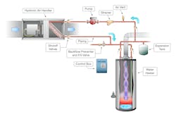
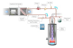
The basic system in this illustration is found throughout the world today. It is a residential or light commercial hydronic air handler connected to a water heater. The circuit for the air handler is tied in with the domestic hot water system. The circulator pump moves water through the air handler loop. A loop is a water circuit through which water exits and enters system or device.
If you’re new to hydronics, study the illustration below and you’ll get much more out of this article. If you’re a total Wethead, have some fun by making a list of the other components you would add to this system to really trick it out. Treat it as you would like to see systems installed in the field.
Water Heating Equipment
This system uses a simple gas-fired water heater. Its purpose is to heat and store the water used throughout the building. Usually a water heater only heats water for potable domestic use, but in this case, there is a water loop piped to the heating system to heat air for the building.
In addition, there are tankless water heaters that may have a secondary circuit for space heating purposes. Boilers used for domestic water heating may also have a secondary loop.
Less conventional water heating systems include; geothermal and solar-powered sources. Some large cities provide a service called “District Heating” where a local utility pipes heated water directly to each customer. The heated water is piped into many heat distribution system types within a building and the customer pays for the hot water consumed.
Hydronic System Pumps
A circulator pump is often used to move water from the water heating source to equipment that distributes its heat to a desired location. Some heating equipment includes the pump shipped internally.
In our system, an air handler is used. The pump is external and moves water from the heat source to the hot water coil in the air handler. A blower moves air across the hot water coil and transfers heat from the hot water into the airstream. The duct system distributes heated air into the building.
There may be one air handler or hundreds of them throughout a building. Of course, the larger the system, the larger the pump, piping, and complexity of controls and other system components. Where a home may use a 1/3 horsepower pump, an office building may use a 100-horsepower pump or larger.
Heating Distribution Equipment
Our simple system uses an air handler as the distribution equipment. There are other types of heating equipment used to distribute heat from hydronic systems into the desired space in the building.
Some of these include:
- Fined tube baseboard and cabinet heaters
- Radiators
- Unit heaters
- Manifolds and control systems connected to in-floor radiant heating
- Snow melt systems.
These are only a few basic systems. More advanced systems include industrial process equipment, medical applications, dehumidification coils and units, and other hydronic heating applications.
Basic System Accessories
Air Vents remove any trapped air in the system. Air in a system may be the most common cause of poor performance. These are installed near the system high point, normally on the pumps return side.
Strainers or hydronic filters are installed in the piping and include circular screens that capture any debris in the system. To clean the strainers, the water is shut off, the screen in the strainer is removed, cleaned, and reinstalled. When the system is refilled, any air introduced into the system must be removed.
Shutoff valves installed at strategic locations in the system isolate components for service or replacement needs. In a basic system, a shutoff valve can be used to reduce or increase flow through the system.
Fill valve and backflow preventer are required accessories where the water source introduces makeup water into the hydronic system. The backflow preventer keeps possible hydronic system pollution from flowing back into the clean water source. Many fill valves include a pressure reducing valve to decrease pressure from the system’s water source.
Expansion tanks provide a space where water can safely expand and contract to avoid damage to the system or occupants. Expansion tanks keep pressure constant to assure controls operate as designed.
Controls and control valves are required and installed with every hydronic system, including a basic thermostat. Depending on the complexity of the controls, the equipment, pump, flow valves, temperature, and zone functions can be adjusted and regulated to effectively regulate a well-designed and installed system.
I’m sure this introductory hydronic system description has left the good Wetheads wanting more about balancing valves, test ports, temperature and pressure gauges, controls and much more.
Hopefully this brief description will encourage the Airheads to dip their toes into the water. Perhaps you hydronic masters will recognize the need and share your valuable knowledge and experience with the Airheads.
Rob “Doc” Falke serves the industry as president of National Comfort Institute, Inc., an HVAC-based training company and membership organization. If you're an HVAC contractor or technician interested in a free balancing valve test procedure, contact Doc at [email protected] or call him at 800-633-7058. Go to NCI’s website at nationalcomfortinstitute.com for free information, articles, and downloads.
About the Author
Rob 'Doc' Falke
President
Rob “Doc” Falke serves the industry as president of National Comfort Institute an HVAC-based training company and membership organization. If you're an HVAC contractor or technician interested in a building pressure measurement procedure, contact Doc at [email protected] or call him at 800-633-7058. Go to NCI’s website at NationalComfortInstitute.com for free information, articles and downloads.


