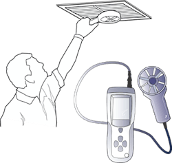
Ideally, you can measure supply register airflow with a balancing hood. But when space is tight or a hood doesn't fit on a register, you can use a traverse technique, and an instrument called an anemometer to measure airflow. Let's take a look at how you can take an accurate and repeatable supply register traverse measurement.
YouTube videos have left many good technicians confused about how to measure supply register airflow because several key principles are missing, and the test is usually oversimplified.
My interest is not to create an argument but to encourage you to gain the knowledge and experience you need. With practice, you can build skills and knowledge for yourself on how to take accurate, repeatable supply register readings in the field that you can trust.
Airflow Traverse
An airflow traverse is the foundation of all airflow measurements. Its core formula is:
CFM = Area x Velocity
- CFM is the volume of Cubic Feet of air passing through a supply register each Minute.
- Area is the open area of the supply register in square feet. You need to make a correction factor to interpret the register open area.
- Velocity is the average airspeed measured through the supply register. Airspeed in the United States is expressed in Feet Per Minute (fpm).
The two challenges you'll face when traversing a supply register are:
1.Accurately measuring average velocity from the register.
2. Finding and compensating for the open area of the supply register.
Test Instruments and Average Velocity
There are two test instruments used in the field to measure the average velocity through a supply register. The most common is a rotating vane anemometer that uses a propeller-style fan to measure average airspeed.Most rotating vanes include a calculating function that enables you to move it back and forth in a pattern over the register's face. You'll take an ongoing velocity reading over the 30 to 60-second test. At the end of the test, the anemometer will display the register's average velocity on its screen.
The other instrument is a thermal or hot wire anemometer. It has a heated wire embedded at the end of an extendable probe. The instrument interprets velocity from the rate heat is removed from the heated wire.
Use this instrument to take and record a series of single-point velocity readings across the register face in a grid pattern. You can program the anemometer to add all your velocity readings together and calculate the register's average velocity.
Measure the entire face of the register as you move the anemometer across it. Make sure you don't allow the probe to move out of the airstream.
Angle and Distance are Critical
Both types of instruments require you to use two test principles to obtain accurate average velocity readings.
First, the measuring device must be held perpendicular (at 90 degrees) to the airflow blowing out of the supply register. If it is not, the velocity reading will be inaccurate. To assure you're capturing the correct velocity, study the register to "see" the air direction. Then rotate your device, so it faces directly into the airstream until it reads the highest velocity.
Second, hold the anemometer an equal distance from the register throughout the test. A consistent one-inch distance is usually recommended. Consistency is the key. As you move closer, velocity will increase. If you drift farther from the face of the register, velocity will decrease. This inconsistency will result in inaccurate readings.
Vena Contracta
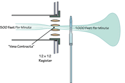
The grand mystery of traversing a supply register is how to compensate for its open area. The louvers on the register face restrict airflow as it exits. This action increases airspeed and is called Vena Contracta. The phenomenon exists at the face of the register, the exact spot where you measure air velocity. So, your airflow calculation has to compensate for it.
Suppose you fail to include a correction factor for the increased air speed in your airflow calculation. In that case, your average air velocity will be artificially high, making your reading higher than what it is.
Each manufacturer publishes correction (Ak) factors that attempt to compensate for the open area of the register. The problem is this published Ak factor rarely agrees with the test instrument, test method, or distance from the grille when you do a traverse. Unfortunately, the published Ak factor cannot be relied on to match your field testing.
You can make your own supply register "corrector" in the field to increase your testing accuracy. It will match all the conditions of how YOU measure supply register airflow.
Make Your Own Correction Factor
To create your customized supply register correction factor, you will need a calibrated commercial balancing hood
Let's assume the supply register you're traversing is inaccessible to a balancing hood. You'll need to find a "sister register" to the one you're traversing. A sister register is the same size and moving similar airflow to the register you're traversing.
Measure the sister register with your balancing hood to find its airflow. Let's say it reads 150 cfm. Then you traverse the sister register and find an average velocity of 300 fpm. (150 ÷ 300 = .50).
With these two readings, you have all the information you need to make a correction factor that matches your test conditions and the supply register.
Next, go to your original supply register the balancing hood was unable to test and traverse it using the same test method you used on the sister register and find its average velocity. Let's say it is 250 fpm. Multiply the average supply register velocity of 250 fpm by your field correction factor of .50 to find the register's true airflow of 125 cfm (250 x .50 = 125).
Build Your Skill, Accuracy, and Confidence
Read this article through once or twice to get started. But to build the skill, accuracy, and confidence in your ability to traverse a supply register takes practice. Check your traverse airflow against your balancing hood and dedicate time to build your skills. This is how you will know for yourself that your airflow readings are accurate.
Rob "Doc" Falke serves the industry as president of National Comfort Institute, Inc., an HVAC-based training company and membership organization. If you're an HVAC professional interested in a free procedure on how to make a grille correction factor, contact Doc at ncilink.com/ContactMe or call him at 800-633-7058. Go to NCI's website at nationalcomfortinstitute.com for free information, articles, downloads, and current training opportunities.


