When I first started in the HVAC industry, superheat and subcooling were two of the most difficult concepts for me to grasp. They just didn’t make sense. I knew how to gather measurements and calculate readings, but that’s where it ended.
With a lot of study and advice from some great mentors, the fundamentals finally added up. Let’s take a look at the basics of superheat and subcooling and how you can accurately measure them.
What Should My Pressures Be?
Some technicians assume their gauges tell them everything they need to know about proper refrigerant charge. That’s one reason many service managers and field service representatives hear the dreaded question, “What should my pressures be?’’
We read evaporating pressure on the left-side manifold gauge (blue if you use colored gauges) with the left hose attached to the suction line service valve. The evaporating pressure represents the point where liquid refrigerant in the evaporator changes to vapor.
We read condensing pressure on the right-side manifold gauge (red if you use colored gauges) with the right hose attached to the liquid line service valve. The condensing pressure represents the point where vapor refrigerant in the condenser changes to a liquid.
Pressures are important; you need them to determine evaporating and condensing saturation temperatures. Saturation is the point where refrigerant changes from liquid to vapor, or from vapor to liquid. When a refrigerant is in this condition, it can’t have any more heat added or removed without changing from one state to another.
You can use refrigerant pressure/temperature (P/T) charts or temperature scales on analog gauges to show the relationship between refrigerant pressure and saturation temperature. Pay attention to it because you will need the saturation temperature to determine superheat and subcooling. One benefit of digital manifolds is that they perform both calculations for you and offer greater accuracy.
Superheat
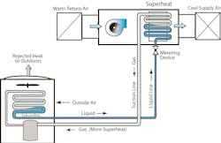
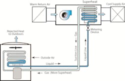
Superheat only affects refrigerant vapor and occurs when heat is added above the saturation temperature. We often use superheat to indicate how much refrigerant vapor is in the evaporator. High superheat means there’s a lot of refrigerant vapor, while low superheat means there’s almost none.
In a properly operating system, you should have cool vapor leaving the evaporator that moves through the suction line, service valve, and into the compressor. There are two kinds of superheat to consider in this flow. One is evaporator superheat, and the other is total superheat.
Total superheat includes evaporator superheat plus additional heat picked up in the suction line between the evaporator and compressor. It’s the type most commonly measured in the field. Many compressor manufacturers recommend a total superheat of 10° to 15°F to assure the compressor doesn’t overheat or suffer from floodback. Consult manufacturer specifications for specific ranges.
If you test a system with a fixed orifice metering device (piston) you need to be extra cautious of your superheat readings. To determine required superheat on a fixed orifice metering device, you must measure entering wet bulb (EWB) temperature at the indoor equipment and outdoor dry bulb (ODB) temperature at the condenser. You can plot these measurements on the manufacturer charging calculator to estimate the recommended superheat range.
Subcooling
Subcooling only affects liquid refrigerant and occurs when heat is removed below the saturation temperature. We typically use it to indicate how much liquid refrigerant is in the condenser. High subcooling means there is a lot of liquid, while low subcooling means there is almost none.
If a system is operating properly, you should have subcooled liquid at the condenser that moves through the liquid line and into the metering device. For A TXV to operate correctly, subcooled liquid refrigerant must enter the valve.
Any premature change from liquid to vapor (flashing) in the liquid line results in reduced system performance. This is one reason we charge systems equipped with TXVs using subcooling. Many manufacturers recommend a subcooling range of 10° – 15°F, but always refer to manufacturer instructions to be sure.
Just as there are two kinds of superheat, there are also two kinds of subcooling. They are condenser subcooling and total subcooling. We usually measure subcooling at the liquid line service valve. This is condenser subcooling, and it represents the amount of heat removed from the refrigerant at the condenser liquid line outlet.
Total subcooling includes additional heat lost in the liquid line between the condenser outlet and the metering device inlet. This accounts for liquid line and filter drier pressure drops and long runs across a hot roof or through an attic.
Measuring Superheat and Subcooling
It’s easy to misdiagnose superheat and subcooling readings when you’re in a rush, so let the system run for at least 10-15 minutes before you check. These simplified steps are for a cooling-only system. If you’re measuring a heat pump in heating mode, they change a little, but the principles stay the same.
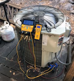
Connect your hoses. Purge your hoses with new refrigerant that matches the type in the system you’re connecting to. Failing to do so will unintentionally introduce moisture and air into the system. It’s wise to follow industry best practices like using low-loss fittings to prevent frostbite.
Once you purge your hoses, connect the hose measuring evaporating (low-side) pressure to the suction line service valve port. Next, connect the hose measuring condensing (high-side) pressure to the liquid line serve valve port.
Attach your temperature probes. You’ll also need to connect temperature probes to the suction and liquid lines near the service valves. The key is to measure line temperatures as near as possible to where you’re measuring pressure.
Clamp-type thermometers work great for these measurements. Higher-quality digital manifolds often have these clamps built in which removes many of the following steps. If you don’t have these accessories, you’ll need to make sure you insulate the temperature probes so they measure line temperature and not air temperature.
First, connect a digital temperature probe to the suction line near the suction line service valve port. Next, connect another digital temperature probe to the liquid line near the liquid line service valve port. Make sure both probes have good contact with the copper lines you’re measuring. Some Bluetooth temperature clamps will flash an indicator to verify your connection. You may need to clean the copper if there’s poor contact.
Calculate superheat. If using analog gauges, find the temperature scale for the refrigerant you’re testing. The evaporating (low-side) pressure will have a corresponding saturation temperature on the gauge. Write this temperature reading down. Next, record the suction line temperature reading from your digital thermometer. It should be higher than the temperature reading on your low-side gauge. Subtract the two temperatures to calculate superheat.
Example: Let’s say you’re measuring a system with R-410a refrigerant, and you have an evaporating pressure of 125 psi. The saturation temperature for this pressure is approximately 43°F. Now you look at your digital thermometer and see the suction line temperature is 53°F. These readings would indicate you have 10°F of superheat (53-43 = 10).
Calculate subcooling. Once you know superheat, you can determine subcooling to see what is happening to refrigerant on the system’s high-side. Once again, if using analog gauges, find the temperature scale for the refrigerant you’re testing. The condensing (high-side) pressure will also have a corresponding saturation temperature on the gauge. Write this temperature down along with the liquid line temperature reading from your digital thermometer. It should be lower than the temperature reading on your high-side gauge. Subtract the two temperatures to calculate subcooling.
Example: Let’s say you’re measuring the same system with R-410a refrigerant, and you have a condensing pressure of 280 psi. The saturation temperature for this pressure is approximately 91°F. Next, you look at your digital thermometer and see the liquid line temperature is 83°F. These readings would indicate you have 8°F of subcooling (91-83 = 8).
Next month, we’ll look at how to use superheat and subcooling to diagnose a system when readings fall outside manufacturer specifications.
David Richardson serves the HVAC industry as director of training at National Comfort Institute, Inc. (NCI). NCI specializes in training that focuses on improving, measuring, and verifying HVAC and Building Performance.
If you’re an HVAC contractor or technician interested in learning more about refrigerant-side performance, contact David at ncilink.com/ContactMe or call 800-633-7058. NCI’s website www.nationalcomfortinstitute.com is full of free technical articles and downloads to help you improve your professionalism and strengthen your company.
About the Author
David Richardson
Director, technical curriculum
David Richardson serves the HVAC industry as director of technical curriculum at National Comfort Institute, Inc. (NCI), Avon, Ohio. NCI specializes in training that focuses on improving, measuring, and verifying HVAC and Building Performance.


