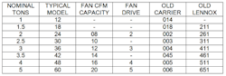
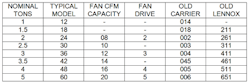
When it comes to diagnosing the airside of a heating or cooling system, start with equipment model number. Once you know the equipment size, you can calculate the required airflow, which is expressed in cfm. (Cubic Feet per Minute) Then you can compare measured airflow to required airflow as the foundation to your diagnostic testing. Equipment size is interpreted by deciphering the model number on the equipment nameplate. The essential model number is normally located on the nameplate data of the outdoor unit for cooling and on the indoor unit for heating. Within the model number are a series of numbers from which you interpret nominal cooling tonnage, or heating Btu input.Cooling Airflow Cooling model numbers are evolving quickly and offer some interesting variety. Cooling airflow is determined by the condensing unit model number if you are working with a split system. The majority of the model numbers have a group of numbers divisible by 12 to represent tonnage. This refers back to the total Btu capacity of 12, 000 Btu per ton. Common nomenclature interprets as follows: 024 represents a 2-ton cooling system or 24,000 nominal Btu 030 represents a 2 1/2 ton cooling system or 30,000 nominal Btu 036 represents a 3-ton cooling system or 36,000 nominal Btu 042 represents a 3 1/2 ton cooling system or 42,000 nominal Btu 048 represents a 4-ton cooling system or 48,000 nominal Btu 060 represents a 5-ton cooling system or 60,000 nominal Btu Once tonnage is identified, multiply the tons by 400 to get total system typical cfm required. Heat pumps typically require 400 cfm per ton in cooling mode and in heating mode. For quite a few years Lennox model numbers were an exception to this rule. They combined Btu and electrical data in their model numbers. For example, a model number containing 411 represented a three cooling Btu rating of about 41,000 with the last 1 representing single-phase equipment. This has been improved upon in recent years. Carrier also used a different method for several years. It seems they started with a 2-ton unit and called it and 002, then numbered each unit up the ladder, sort of. Some manufacturers now include a number in their model numbers that simply includes the tonnage of their fan drive. For example a 3 imbedded in a model number indicates a 3 ton or 1200 cfm fan drive. These numbers indicate airflow under certain conditions however. The conditions are normally that if the fan is set at high speed and if the system static pressure is at or below the fan maximum rated total external static pressure, 400 cfm per ton can be expected. Of course referring to the manufacturer’s engineering data and field measuring system performance is the only way to be absolutely certain. The table below will help you interpret a majority of the cooling nomenclature you’ll see in residential systems today.
With a little practice you’ll soon begin to see the patters in equipment nomenclature and you’ll soon be able to interpret tonnage at a glance.Heating Airflow Most heating equipment model numbers refer to the Btu input somewhere in the model number. It’s most often a number divisible by 20 or 25. These numbers represent thousands of Btu’s of gas input. For example, a model number containing 100, represents a 100,000 Btu gas input. 080 represents 80,000 Btu gas input. Multiply the gas input by the equipment AFUE rating to determine the potential Btu output of the equipment. For example 100,000 Btu input times the AFUE rating of 90% equals an output of 90,000 Btu’s. Heating airflow can be calculated several ways. The easiest method we have found is the cfm per 10,000 Btu of input method. Example: An induced draft furnace should move 130 cfm per 10,000 Btu at sea level. So, say we have a 100,000 Btu Input induced draft furnace. To find required airflow divide the rated furnace input by 10,000 Btu. 100,000 divided by 10,000 equals a factor of 10. 10 Times 130 cfm equals 1300 cfm. This airflow rule is applied to determine furnace airflow for three types of furnaces. Condensing furnaces require 150 cfm per 10, 000 Btu input. Induced draft furnaces require 130 cfm per 10,000 Btu input, and natural draft furnaces require 100 cfm per 10, 000 Btu input. Back to our original point, in order to completely diagnose the performance of an HVAC system, airflow not only over the coil, but through the registers and grilles must be known. You can identify the required airflow through a system be interpreting the model number and using simple multiplication applying the rules described in this article.Rob “Doc” Falke serves the industry as president of National Comfort Institute a training company specializing in measuring, rating, improving and verifying HVAC system performance. If you're an HVAC contractor or technician interested in a free HVAC industry cooling nomenclature table through 25 tons, contact Doc at [email protected]">[email protected] or call him at 800-633-7058. Go to NCI’s website at www.nationalcomfortinstitute.com for free information, technical articles and downloads.
About the Author
Rob 'Doc' Falke
President
Rob “Doc” Falke serves the industry as president of National Comfort Institute an HVAC-based training company and membership organization. If you're an HVAC contractor or technician interested in a building pressure measurement procedure, contact Doc at [email protected] or call him at 800-633-7058. Go to NCI’s website at NationalComfortInstitute.com for free information, articles and downloads.
Sign up for our eNewsletters
Get the latest news and updates