Minimizing Ammonia Charge in Industrial Refrigeration Systems

Ammonia has been and continues to be the predominant refrigerant used in the cold storage and food processing industry. However, as a result of industrial accidents, the potential as a terrorist target, drug trafficking, and growing local concerns, its use has come under increased scrutiny over the past decade.
From a pure technical and environmental perspective, the benefits of ammonia as a refrigerant are unparalleled. It is a natural refrigerant with no global warming or ozone depletion potential.
To minimize the risks associated with large ammonia charges, engineers, contractors and equipment supplies are working to find new and innovative ways to minimize their ammonia system charges.
Given the variety of systems under review, it was a significant challenge to compare these systems on a like basis. This effort was facilitated to some degree by a paper written by Jeff Welch of Welch Engineering Corporation. In his paper, Welch compares a “typical” cold storage facility with that of an Advanced Direct Expansion central system (one of the systems reviewed in this document). Using the same approach as Welch used in his paper in creating this hypothetical system and thanks to the many contributors to this document, a reasonable comparison between systems was made possible.
Description of Baseline System
The facility design under consideration is described below:
• Designed as a conventional two-stage pumped recirculated liquid (PRL) system.
• Building: 112,000 ft2, 400-ft. wide by 280-ft. deep by 30-ft. high, with a 20-ft. high dock
Loads:
• Freezer: 283 tons at -10F.
• Blast Cells: six, at 65 tons each, designed to freeze a truck load of product to 0F in 24 hours. It is anticipated that blast temperatures would typically fall into the range of -30F.
• Dock: 80 tons at 45F.
• The total refrigeration load for the facility is estimated to be 753 tons (9,036,000 BTUH)
• This particular system would best be described as a “soft” optimized pumped recirculated liquid system. For the purposes of this report, it shall be referred to as the Baseline System or PRL. The ammonia charge for this design is estimated at 15,147 pounds or 20.1 pounds of ammonia/ton of refrigeration. As a result of the conservative nature of the industry, a more typical scenario for this type of system would be 17, 314 pounds or 23 pounds of ammonia/ton of refrigeration.
I. Advanced Direct Expansion
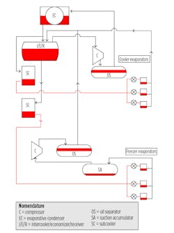
Direct Expansion (also known as Dry Expansion or DX) systems have been in use in refrigeration and air conditioning for decades. Until recently, the use of DX in ammonia based industrial refrigeration systems has been quite limited. (See Fig. 1)
There are a number of technical reasons behind the historical lack of DX systems in industrial refrigeration however; the topic is beyond the scope of this paper. Rather, the focus on DX systems will be its reemergence as a solution to the problem of high ammonia inventories. This revival has come primarily as a result of recent technical advancements. For the purposes of this discussion, the Direct Expansion (DX) system considered in this document will focus on the Colmac Coil approach which incorporates the latest advancements related to:
• Heat transfer
• Liquid distribution
• Electronic control
• System optimization
As noted, the DX system falls into the category of a central system. However, the very nature of a DX system leads to a much more prudent use of ammonia than in the baseline pumped ammonia system. The result is a dramatic reduction in ammonia charge.
A properly designed DX system will:
• Utilize fewer vessels
• Utilize fewer pipes
• Utilize smaller pipe diameters
• Require no pumps.
What’s Different?
In comparing a DX system to a pumped system, the reader will likely note more similarities than differences. The key difference between the two systems is that the high pressure liquid in a DX system is fed directly to each evaporator via an expansion device at the evaporator inlet. The heat transfer objective of the evaporator is to vaporize all of the liquid before it leaves the evaporator. While there are many differences in terms of ammonia inventory between the two systems, the 3 main components in a pumped system which hold excess refrigerant are:
• The recirculator vessel
• The evaporator
• The piping system entering and leaving each evaporator from/to the recirculator vessel.
DX System Ammonia Refrigerant Charge
In his paper, Jeff Welch estimated the charge of a baseline pumped system and an equivalent DX system. The DX system had an ammonia charge of 6053 pounds. On a per ton basis, this translates to roughly 8 lbs. of ammonia/ton of refrigeration or about 40% of the charge of an optimized pumped system. A new, all DX facility was recently commissioned in the Midwest USA. The design of the facility was similar to the hypothetical system and resulted in an ammonia charge of approximately 7.5 pounds per ton of refrigeration. The author has visited the new facility and is aware of the reasons for the difference in charge. For the purposes of this generalized discussion, the charge for the DX system will be set at 7.5 pounds/TR.
II. Hybrid Systems CO2/NH3 Cascade
The type of system described as “CO2/NH3 cascade” isolates the ammonia refrigeration part of the system to the machine room. As with all refrigerants, the higher the temperature of the refrigerant, the higher the operating pressure. In order to limit the extremely high pressures necessary for an all-carbon dioxide (CO2) system, the ammonia part of the system provides the initial condensing for the CO2 system and thereby limits the pressure which would exist if CO2 were to be condensed as in a typical refrigeration cycle (95F condensing temperature, typically). The evaporator for the ammonia system is also the condenser for the CO2 system. This type of heat exchanger is referred to as a cascade heat exchanger and can be constructed in a number of different ways:
• Shell and tube
• Welded plate
• Shell and plate
The choice of style will have a direct impact on the refrigerant charge of the system with shell and tube requiring the most refrigerant and welded plate requiring the least refrigerant.
There are several different approaches taken in achieving the desired temperature levels of the coolers and the freezers. The methodology for this particular configuration has been as follows:
1. Cool the CO2 down to the temperatures required by the coolers through the cascade heat exchanger and send to the CO2 recirculator vessel.
2. Move the cool liquid to the coolers and freezers
a. Pump some of the condensed CO2 to the cooler coils from the cascade heat exchanger. Unlike ammonia, recirculation rates are maintained much closer to 1:1, allowing almost all of the CO2 to be evaporated. This has the added benefit of reducing the size of the evaporator and the horsepower of the pump.
b. Supply additional liquid from the CO2 recirculator to the freezer coils. Each coil is equipped with an electronic expansion valve to lower the temperature and pressure of the CO2 to the desired temperature
3. Return the gas/liquid mixture from the cooler coils and the freezer coils to the CO2 recirculator.
4. The vapor collected in the recirculator is then sent back to the CO2 compressor, compressed and sent to the cascade heat exchanger to be condensed while the liquid is circulated back to the coolers and freezers.
The system is relatively simple and doesn’t require much more equipment than a two-stage pumped recirculated system would. As will be noted below, due to some of the thermophysical properties of CO2, there can be some significant savings on the equipment for this type of system. Additional advantages offered by CO2 as a refrigerant arise from its high heat transfer coefficient at very low temperatures and favorable vapor to liquid volumetric ratios. This leads to:
• More efficient cascade heat exchanger (reduced energy consumption due to a smaller temperature difference requirement)
• Smaller evaporators
• Lower recirculation rates
• Smaller pumps
• Reduced pumping power demands
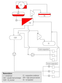
As seen in Figure 2, all of the ammonia is confined to equipment residing in the machine room. The reader should note that a great deal of detail has been purposely left out of the sketch in order to focus on the basic process.
Ammonia Refrigerant Charge
From Figure 2, note that all of the ammonia charge for this system is isolated to the machine room. As previously pointed out, the ultimate ammonia charge will depend on several factors:
• the type of cascade heat exchanger
• type of condenser
• The size and amount of piping connecting the CO2 and NH3 systems.
While it has been estimated that the ammonia charge in a system like this can be, potentially, reduced to as low as 10% of the ammonia charge in a typical pumped recirculated liquid system, the actual numbers are likely to much higher than this theoretical value. Fortunately, data exists on existing CO2/NH3 cascade systems which provide actual experiences. US Cold Storage currently has seven CO2/NH3 cascade facilities in operation and two more under construction. They have been kind enough to share their experiences with the cold storage community. Information provided in this report does not represent any individual USCS facility but rather represents data on an aggregate basis. With respect to ammonia charge, the typical ammonia charge in the USCS facilities is approximately 8 lbs./ton of refrigeration. The reader will note on the summary page that the theoretical value for this type of system is about 25% lower than those reported by USCS. There are a number of possible explanations for the difference between the USCS facilities and the theoretical values. A broad generalization would suggest a charge of between 4 and 6 lbs./TR. It is clear that while 4 lbs./TR is achievable, it may not be the most practical objective. For the purposes of this report, the charge will be conservatively estimated at 6 pounds/TR.
Next month, Part 2 of this article will discuss a second hybrid system, CO2/NH3 with pumped volatile brine (PVB), as well as three types of packaged systems: an air- and water-cooled NH3 packaged chiller, an air-cooled condensing unit, and a self-contained refrigeration system.
Terry L. Chapp, PE, is national business-development manager for Danfoss Industrial Refrigeration. He has been involved in all aspects of HVACR, with particular emphasis on heat exchangers, valves, and controls, over the last 35 years.
References
Welch, J. (2013). DX evaporator installation – Final project report. Retrieved from http://bit.ly/Welch_DX
Nelson, B.I. (2013). DX ammonia piping handbook. Colmac Coil Manufacturing. Retrieved from http://bit.ly/Nelson_DX
PG&E. (2009). Cascade C02/NH3 refrigeration system efficiency study. PGE 0707. Emerging Technologies Coordinating Council.