If I could make a wish, it would be to stand beside every new HVAC tech as they began work on their first system. I would have the fan table taped to the front of the unit and teach the most important task in troubleshooting - to measure the system’s total external static pressure and plot fan airflow. That technician would immediately catapult past most 20-year veterans. Let’s take a look at how you can learn just what I would teach every new HVAC technician.
The most important diagnostic fact you can discover about a system is to determine the amount of air the fan is moving. Airflow is the answer to more than 70% of poorly performing systems. Measuring airflow can be completed in just a few minutes using the manufacturer’s published fan table.
Most of these tables are available on your smart phone via the Internet. Once you get good at it, you can discover fan airflow within a few minutes of testing.
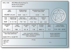
Read and Interpret the Nameplate
Each air-moving piece of equipment has a nameplate from which you will read and record the equipment model number. This is the number you’ll use to interpret required airflow needs based on tonnage of the outdoor equipment (See the free NCI Nomenclature Chart at the end of this article).
Fan Speed Setting
The last piece to plotting fan airflow is the fan speed setting. This can be found by inspecting the dip switch settings and interpreting the fan speed setting in the installation instructions.
If the fan uses a circuit board with plug-in speed taps, interpret fan speed setting by reading the wiring schematic on the back of the blower compartment door.
Using this information, you can find the model number of the equipment on the fan tables and identify the maximum rated pressure the fan can handle.
Measure Total External Static Pressure
At the top of most residential fan tables you’ll find columns showing total external static pressure (TESP) values in tenths of an inch water column. To look up or plot the fan airflow, you’ll need to measure the system’s TESP. Here’s how it’s done.
- STEP ONE: Prepare to measure system TESP by installing two test ports. Always inspect behind where the test ports will be installed to find a safe spot. Drill two 3/8” access holes where air enters the air moving equipment and where air exits the equipment.
Use a form of drill-bit protection, such as a sheath, that prevents the drill bit from penetrating too deeply and damaging a cooling coil or circuit board. If you’re a technician, e-mail Doc for a free static pressure test procedure.
- STEP TWO: Start the fan by energizing the equipment at the thermostat. This can be done by setting the thermostat to cooling mode and 55F.
In heating mode, set the fan to 85F and the fan will continue to run while you measure static pressure. If the fan uses a variable-speed motor, allow the fan to ramp up to full speed before measuring static pressure.
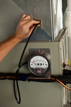
Test Instrument Requirements The test instrument you’ll need is called a manometer. Hopefully, you’ll find one lying around the shop.You’ll also need one or two pieces of tubing (through which the pressure travels from inside the equipment to the manometer) and a static pressure tip that inserts into the test port and gathers the static pressure reading from the air stream.
- STEP THREE: Connect the tubing to the manometer. Attach the tube going to the test port entering the equipment to the bottom or left port on the manometer. And then attach the tube going to the test port exiting the equipment to the top or right port on the manometer.
The manometer will add together the pressure in the two test ports and display measured total external static pressure.
Read and record the system total external static pressure. You will use the TESP to plot fan airflow in the fan table.
Plot Fan Airflow
Having interpreted the equipment nominal tonnage, interpreted the fan speed setting, and measured TESP, you are ready to plot fan airflow on the fan table.
Circle the fan speed setting, normally located on the left side of the fan table.
Next, circle the TESP on the top of the fan table that is closest to the measured system static pressure you recorded from the display of the manometer.
Finally, connect the circles on the fan table by drawing a horizontal line to the right of the fan speed setting until you intersect with the column of the measured total external static pressure.
Then draw another line down from the measured static pressure circled at the top of the fan table until it almost connect with the fan speed line. The fan airflow is found where the two lines intersect.
Congratulations, this is the amount of airflow the fan is moving.
Compare the plotted fan airflow to the required airflow of the system. Don’t freak out, if the airflow you plotted is only 60% of required system airflow.
If measured TESP is higher than the rated TESP, resistance in the system is causing low airflow.
High measured TESP can be caused by many problems. The most common ones are:
• Restrictive air filters
• Plugged cooling coils
• Undersized ducting.
A similar test can be easily completed to measure the pressure drop, or resistance to airflow of each component in the system, but that’s another article.
Each of these restrictions can easily be repaired. The hard part is learning to test and interpret your pressure readings. Pinpointing the problem is the test that few technicians have taken the time to master.
How Much Time?
The first time you complete this test, it may take you a half hour or more. Each step seems painstakingly difficult and clumsy. At least it did for me, my first time few times.
Very soon, your skill begins to develop and you’ll find yourself executing each of these steps automatically in 10 minutes or less. The best part is once you master this test, you will be able to “see” the reason you may have been mis-diagnosing systems your entire career.
Fan tables reveal hidden airflow secrets that only the best technicians are able to see.
Rob “Doc” Falke serves the industry as president of National Comfort Institute an HVAC-based training company and membership organization. If you're an HVAC contractor or technician interested in a free NCI Nomenclature Chart, contact Doc at [email protected] or call him at 800-633-7058. Go to NCI’s website at nationalcomfortinstitute.com for free information, articles, and downloads.
About the Author
Rob 'Doc' Falke
President
Rob “Doc” Falke serves the industry as president of National Comfort Institute an HVAC-based training company and membership organization. If you're an HVAC contractor or technician interested in a building pressure measurement procedure, contact Doc at [email protected] or call him at 800-633-7058. Go to NCI’s website at NationalComfortInstitute.com for free information, articles and downloads.


