A constant stream of evidence confirms performance losses up to 30% from roof curbs due to poor manufacturing, installation, or maintenance. Such curb defects reduce the performance of a 14-EER unit to a system performing below 10 EER. The problem is, unless you look for it, curb defects and the resulting efficiency losses are invisible.
How Does a Curb Function?
Roof curbs are accessories resembling a pedestal that sit below a rooftop-packaged unit. A well-designed and installed curb provides a transition for the supply and return air from the unit to the air distribution system.
In theory, a properly built and installed curb should have little effect on airflow through the system. In an ideal world, there should also be no temperature change through the curb. However, any difference in the air temperature entering or leaving a curb signals the possibility of leakage from outside the curb into the airstream. It can also indicate air bypassing between the supply and return ducts within the curb.
The Most Common Curb Defects
Because the curb constitutes less than two feet of the typical duct system, you may assume it has little effect on system performance. The purpose of this article is to change that assumption.
In the field, we’ve found new construction curbs have little negative impact because a new project is built from scratch. The manufacturer builds a curb matching the equipment and duct penetrations are custom built to match the curb. The roofer professionally ties the new curb into the new roof so there is little chance of an air or water leak.
Airflow Losses -- Curb problems often begin when equipment is replaced. An aftermarket curb is often used to connect the footprint of the old unit to the footprint of the replacement unit. Since the average curb height is only 12 inches, the curb manufacturer whips up a 12-inch transition connecting the replacement unit to the roof with little regard for airflow.
If the discharge duct of the unit is offset 24 inches from the supply duct roof penetration, to meet SMACNA duct standards, the roof curb would need to be 48 inches tall. So, low-bid work often takes these shortcuts and gets low-bid results with a 30% reduction in airflow.
Temperature Losses – Curb leakage is often the result of sloppy work during equipment replacement. Aftermarket curbs are included in hopes of reducing the amount of required labor. Since the labor budget is “blow-and-go,” the care and attention needed to assure good workmanship is missing.
Improperly sealed return duct curb penetrations are very close to the fan where duct system pressures are highest. Highest pressure equals increased leakage. Air can be pulled into the duct system from a hot attic, or directly from outside.
Leakage between the supply and return inside the curb is another serious problem that is often impossible to see once the unit is set. The result is very poorly performing equipment shutting off on high limit or a screwed-up refrigeration charge.
Pressure Testing to Discover Curb Airflow Restrictions
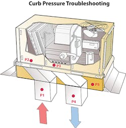
The first test: measure pressure drop of the supply and return duct through the curb.
Do this by installing test ports in the supply and return before and after each duct enters the curb.
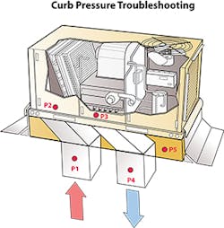
Field measurement has documented supply and return duct pressure drop through the curb in a well performing system averages less than 10% of fan rated pressure. An example of this is a system where the fan was rated at .50”, the pressure drop of the supply and return duct combined through the curb would be no more than .05”. If the measured pressure were higher than this rule of thumb, system airflow could be lower than required.
To correct this problem, the duct needs to be oversized throughout the system to compensate for the excess resistance to airflow.
Test port P5 shows one additional pressure test that may indicate air leakage within a curb. Install a test port into the hollow area of the curb. Drill the hole behind the flashing to assure there is no water access into the curb. Connect the tubing to your manometer and measure the pressure within the curb. Ideally, the pressure should be zero.
If the pressure within the curb is positive, this indicates a supply duct leak. If the curb’s internal pressure is negative, this indicates a dominant return duct leak. You can normally get access to the duct within the curb by reaching down through the equipment.
Temperature Testing to Identify Curb Airflow Leakage
When equipment is set on the curb, several opportunities for leakage can be created. These include:
- The equipment and curb don’t line up and the subsequent gaps cause air leakage.
- The duct connections within the curb become damaged and will not seal.
- Installers fail to seal the connection at the equipment and the ducting connected to the curb.
- Gasket material gets twisted or damaged and fails to seal correctly below the unit.
- When both ducts within the curb fail to seal, an unseen air bypass is created. This changes the equipment entering air temperature and may seriously deteriorate the heating or cooling capacity of the equipment.
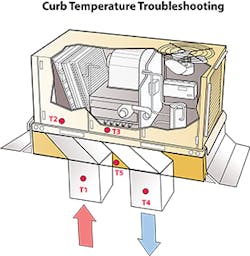
Refer to the Curb Temperature Troubleshooting Illustration above. Subtract to find the temperature difference between T1 and T2 to identify temperature loss or gain in the return duct. To find leakage in the supply duct subtract to find the temperature difference between test ports T3 and T4. Test port T5 can identify any bypass by measuring the temperature in the hollow area of the curb.
As you apply these testing and troubleshooting principles to the curbed systems you service, sell, and install, you will be able to correct invisible defects that have gone undetected for decades.
Rob “Doc” Falke serves the industry as president of National Comfort Institute -- an HVAC-based training company and membership organization. If you have additional comments or questions about performance diagnostics, contact Doc at [email protected] or call him at 800-633-7058. Go to NCI’s website at nationalcomfortinstitute.com for free information, articles, and downloads.
About the Author
Rob 'Doc' Falke
President
Rob “Doc” Falke serves the industry as president of National Comfort Institute an HVAC-based training company and membership organization. If you're an HVAC contractor or technician interested in a building pressure measurement procedure, contact Doc at [email protected] or call him at 800-633-7058. Go to NCI’s website at NationalComfortInstitute.com for free information, articles and downloads.